|
The NCE DCC Packet Analyzer tool works with the NCE Packet Analyzer product to read and present the DCC packets on your track. It connects via a separate serial port from your command station connection. If you do not have an NCE system, configure a new second connection in Preferences->Connections to "NCE Simulator" so you can access the NCE "DCC Packet Analyzer" menu item. If you do this, you will need to restart JMRI and then open Preferences->Defaults to check that the NCE Simulator has not "stolen" any of your real connections. |
|
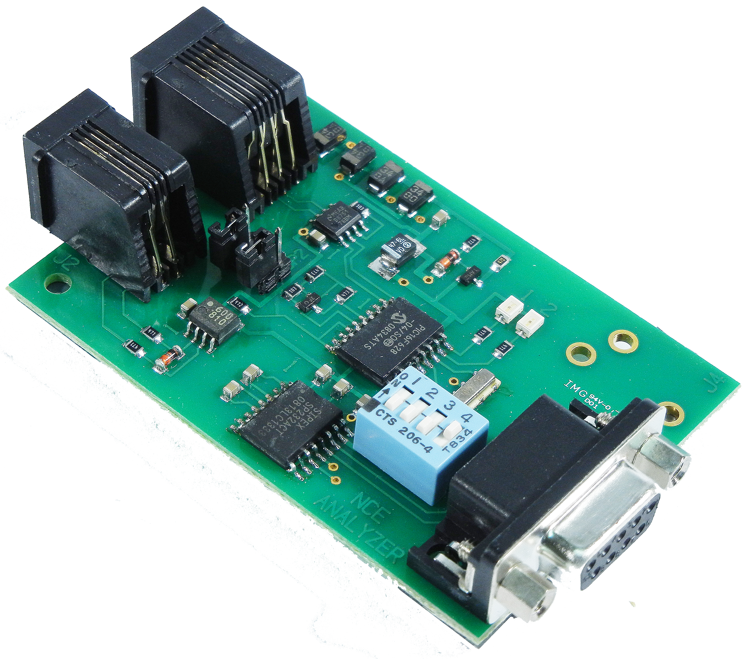
There are two versions of the analyzer. The original that was sold as a PC board came out around 2002. It used serial port at a fixed 38.4Kbps. The new DCC Meter/Analyzer was released in 2023. It uses a USB port for the analyzer connection but also has a display for being a DCC amp and volt meter.
Select the "Serial port:" and select which model of Analyzer you have. That selection will configure the serial port for the right settings for that device. Next push the "Open" button. This will then unlock all of the radio buttons. If nothing appears on the screen immediately, select a new display mode (e.g. "Verbose") and some packet types to display (e.g. "Idle Packets").
Use the radio buttons to configure the analyzer to your liking. Note that the NCE analyzer will remember the configuration when it is powered down. The default is to not show anything. Typical use would want the "Show loco packets" selected.
The check box for filtering duplicate packets, "Hide duplicates", will count how many repeats there were. When a different packet happens, it will print the duplicated packet with a trailing count shown as " [nn] " meaning it was repeated nn times. It with then print the new packet. The time stamps for the duplicate packet will be that of the new packet, not the time stamp of the last duplicate packet.
The following help was copied from NCE Corporation with their permission. It is for the original version of the Packet Analyzer. Click here to download the full Analyzer manual.
Commands:
V Display packets in 'verbose' mode (able to be intrepreted by humans)
H Display packets as hex bytes
H0 Set hex display mode 0 (see hex display table)
H1 Set hex display mode 1 (see hex display table)
H2 Set hex display mode 2 (see hex display table)
H3 Set hex display mode 3 (see hex display table)
H4 Set hex display mode 4 (see hex display table)
H5 Set hex display mode 5 (see hex display table)
H6 Set hex display mode 6 (see hex display table)
H7 Set hex display mode 7 (see hex display table)
A+ Display all accessory packets
A- Don't display accessory packets
I+ Display all idle packets
I- Don't display idle packets
L+ Display all locomotive packets
L- Don't display locomotive packets
R+ Display all reset packets
R- Don't display reset packets
S+ Display all signal packets
S- Don't display signal packets
? Display list of commands supported
The analyzer remembers the last display mode after power up.
H1 mode:
Same as H0 mode except spaces will delimit preamble char and each pair of hex characters.
Example: $ 03 68 6B
14 start bits with three byte packet following with bytes of 0x03, 0x68, 0x6B
H2 mode:
Displays packets in hex mode with no indication of how many preamble bits. There are no
spaces between any characters or bytes.
Example: 03686B
Three byte packet following with bytes of 0x03, 0x68, 0x6B
H3 mode:
Same as H2 mode except spaces will delimit each pair of hex characters
Example: 03 68 6B
Three byte packet following with bytes of 0x03, 0x68, 0x6B
H4 mode:
Displays packets in hex mode preceded by Pxx where xx indicates how many preamble bits (in
hex). There are no spaces between any characters or bytes.
Example: P0E03686B
14 start bits with three byte packet following with bytes of 0x03, 0x68, 0x6B
H5 mode:
Same as H4 mode except spaces will delimit preamble chars and each pair of hex characters
Example: P0E 03 68 6B
14 start bits with three byte packet following with bytes of 0x03, 0x68, 0x6B
H6 mode:
Displays packets in hex mode with no indication of how many preamble bits but preceded by the
letter P. There are no spaces between any characters or bytes.
Example: P03686B
Three byte packet following with bytes of 0x03, 0x68, 0x6B
H7 mode:
Same as H6 mode except spaces will delimit each pair of hex characters
Example: P 03 68 6B
Three byte packet following with bytes of 0x03, 0x68, 0x6B
Reset packets will be displayed as: "RESET"
Idle packets are displayed as: "IDLE"
Format of locomotive speed packets: L1234 S123F
A short loco address is displayed with 3 digits (ie, L003) and a long address is displayed
with 4 digits (ie.L1234).
14/28 speed commands are displayed with 2 digits (S08) and 128 speed commands are displayed
with 3 digits (S123). The last character displayed is the direction. F for forward and R for
Reverse.
Emergency stop packets are displayed as such: L1234 ESTOP.
Format for locomotive function group 1 packets: L1234 FL1234
Short and long locomotive addresses are are indicated by 3 or 4 digits as in speed packets.
The function numbers, if off, are indicated by a dash (-). If on the function numbers are
indicated by L for F0 and 1-4 for F1-F4.
Example: L1234 F--32- means function 2 and 3 are on and function 0,1 and 4 are off.
Format for locomotive function group 2 packets: L1234 F8765
Short and long locomotive addresses are are indicated by 3 or 4 digits as in speed packets.
The function numbers, if off, are indicated by a dash (-). If on the function numbers are
indicated by 5-8 for F5-F8.
Example: L1234 F8-6- means function 8 and 6 are on and function 5 and 7 are off.
Format for locomotive function group 3 packets: L1234 FCBA9
Short and long locomotive addresses are are indicated by 3 or 4 digits as in speed packets.
The function numbers, if off, are indicated by a dash (-). If on the function numbers are
indicated by 9,A,B,or C for F9-F12.
Example: L1234 FC-A- means function 12 and 10 are on and function 9 and 11 are off.
Format for locomotive function group 4 packets: L1234 FKJIHGFED
Short and long locomotive addresses are are indicated by 3 or 4 digits as in speed packets.
The function numbers, if off, are indicated by a dash (-). If on the function numbers are
indicated by D,E,F,G,H,I,J,K for F13-F20.
Example: L1234 F----G-E- means functions 14 and 16 are on.
Format for locomotive function group 5 packets: L1234 FSRQPONML
Short and long locomotive addresses are are indicated by 3 or 4 digits as in speed packets.
The function numbers, if off, are indicated by a dash (-). If on the function numbers are
indicated by L,M,N,O,P,Q,R and S,T for F21-F28.
Example: L1234 F----O-M- means functions 22 and 24 are on.
Format for locomotive long form OPS write byte: L1234 CV0044=123
Short and long locomotive addresses are are indicated by 3 or 4 digits as in speed packets.
The CV number in the above example is 44 (always displayed with 4 digits) and the value for
the CV is 123 (always displayed with 3 digits).
Format for locomotive long form OPS write bits: L1234 CV0044 b3=1
Short and long locomotive addresses are are indicated by 3 or 4 digits as in speed packets.
The CV number in the above example is 44 (always displayed with 4 digits) and bit 3 is to be
programmed to a 1.
Format for locomotive long form OPS verify byte: L1234 OPS VFY
Short and long locomotive addresses are are indicated by 3 or 4 digits as in speed packets.
The command is not completely decoded by the analyzer
Format for locomotive short form OPS write byte: L1234 CV23=123
Short and long locomotive addresses are are indicated by 3 or 4 digits as in speed packets.
The CV number in the above example is 23 (only CV23 or CV24 can be programmed with short
form) and the value for the CV is 123 (always displayed with 3 digits). If the analyzer
doesn't understand the CV number indicated it will display L1234 OPS?
Format for consist control setup packets: L1234 CON=123R
Short and long locomotive addresses are are indicated by 3 or 4 digits as in speed packets.
In the example above CV19 (consist address) will be set to 123 with the direction of
operation to be reverse.
Format for accessory control (paired outputs): A1234N
The accessory address is always displayed with 4 digits. "N" or "R" follows to indicate
normal (on) or reverse (off) for the turnout position.
Format for accessory OPS write byte (legacy Ops mode):
A1234*CV0513=123
The accessory address is always displayed with 4 digits. The CV number in the above example
is 513 (always displayed with 4 digits) and the value for the CV is 123. The distinction
between legacy mode and new mode (see below) is the asterisk (*) between the accessory
address and the CV address for legacy mode.
Format for accessory OPS write byte (new Ops mode): A1234 CV0513=123
The accessory address is always displayed with 4 digits. The CV number in the above example
is 513 (always displayed with 4 digits) and the value for the CV is 123. Only the write byte
portion of this command is decoded by the analyzer. The distinction between legacy mode (see
above) and new mode is the asterisk (*) between the accessory address and the CV address for
legacy mode
Format for signal ("extended" accessory addresses) control: S1234 2F
The signal address is always displayed with 4 digits followed by the signal aspect byte
displayed in hex.
Format for signal OPS write byte: S1234 CV0513=123
The signal address is always displayed with 4 digits. The CV number in the above example is
513 (always displayed with 4 digits) and the value for the CV is 123. Only the write byte
portion of this command is decoded by the analyzer.