JMRI needs to know how a Signal Head on the layout is connected to the electrical hardware. Once JMRI knows that, it can send the right DCC commands to control the Appearance of a Signal Head.
The "Edit Signal Head" panel provides for viewing and changing optional information for existing Signal Heads. Use the "Edit" button in the Signal Head Table to open a dialog for that Signal Head. Only one Signal Head may be edited at a time. Signal Type and Signal System may not be changed once they have been created. After making changes in the dialog, click the "Update" button at the bottom of the panel to change Signal Head information. Click "Cancel" to exit without making any changes. Closing the Edit Signal Head panel is equivalent to clicking "Cancel".
The "Add New Signal" dialog that is opened by clicking on the "Add..." button at the bottom of the Signal Head Table lets you choose a Signal Head Connection type from the following list.
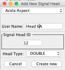 Acela
Acela
In the text field, enter a System Name for an Acela signal head, e.g. AH01. For more information on Acela hardware, see the Acela hardware help page.
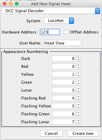
Enter the DCC address as a number. The Offset Address check box uses an alternative
interpretation of the addressing scheme that might be in use.
Each possible Appearance of the Signal Head is assigned a different number; from here
you can assign different numbers for each Aspect to suit the hardware being used.
The Team
Digital SHD2 Signal Decoder is a Signal Head decoder using a different address for
each Signal Head. A Signal Mast attached to the SHD2 must be configured as one or more
Signal Head controlled masts using the DCC Signal connection type. Instructions can be
found on the Team Digital website under the Applications
> SHD2 menu.
Note: The Signalist SC1 can also be configured as individual Signal Heads (searchlight
with bicolor, tricolor or RGB LEDs or multi-lamp with individual LEDs), but is much
easier to use when configured as a complete Signal Mast with all Signal Heads on a single
DCC address using the DCC Signal Mast driver.
In that case you don't need to add Signal Heads for your signal. Key difference between a
Signal Head and a Signal Mast is the number of different states each might have. A Signal
Head only has (up to) 8 Appearance entries, but a Signal Mast can have up to 32 (0-31)
possible states, called Aspects in that case. The command going out is the same but the
number of possible values differs.
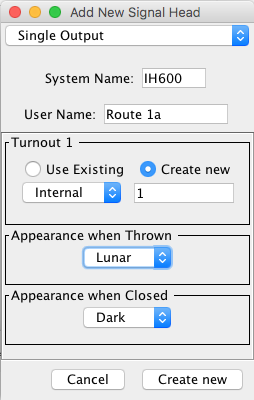
For each connection, enter the appropriate JMRI Turnout for the electrical connection on the layout, either from the drop down list of already-defined Turnouts or by creating a new Turnout for a particular connection.
Select one of the listed Appearances for both:
Appearance when Thrown - The appearance displayed when the connection is in the Thrown
State.
Appearance when Closed - The appearance displayed when the connection is in the Closed
State.
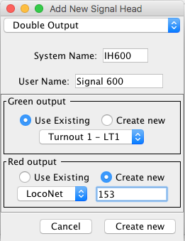
For each connection, enter the appropriate JMRI turnout for the electrical connection
on the layout, either from the drop down list of already-defined turnouts or by creating
a new turnout for a particular connection. They need not be consecutive or in any
particular order.
A Signal Head connection that uses just two output lines can indicate 4 or more signal
Aspects.
Usually these Aspects will be Clear, Approach, Stop, and Dark. Flashing each adds more
aspects. Use this head to create a Signal Head Controlled Mast as a next step.
The output coding is such that one turnout Thrown (On) controls the Stop and the other
Thrown (On) controls the Clear. Both outputs Thrown (On) controls the Approach, and both
Closed (Off) is Dark. Each full aspect change requires that two turnout commands be
sent.
For each connection, enter the appropriate JMRI turnout for the electrical connection
on the layout, either from the drop down list of already-defined turnouts or by creating
a new turnout for a particular connection. They need not be consecutive or in any
particular order.
If you need to debug one of these Signal Heads, start by checking whether the Turnout
connections work.
For each connection, enter the appropriate JMRI Turnout for the electrical connection on the layout, either from the drop down list of already-defined Turnouts or by creating a new Turnout for a particular connection. They need not be consecutive or in any particular order.
For each connection, enter the appropriate JMRI Turnout address for the electrical connection on the layout, either from the drop down list of already-defined turnouts or by creating a new turnout for a particular connection. They need not be consecutive or in any particular order.
This type controls Signal Heads attached to a Digitrax SE8C signal driver card.
Because each SE8C 4 Aspect Signal Head works with a specific DCC address, its System Name is determined automatically from that address; you don't have to enter it. For example, the SE8C 4 Aspect Signal Head for hardware address 257 will be given a system name based on that. See page 5 through 7 of the Digitrax SE8C Manual.
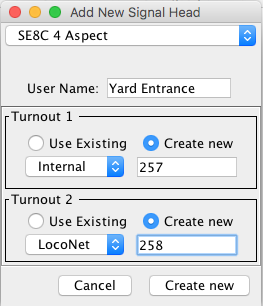 You can optionally
enter a more readable User Name if you'd like.
You can optionally
enter a more readable User Name if you'd like.
In the "Turnout number" box, enter the appropriate DCC address of the SE8C output as a number. For example, the 1st signal head on the 1st SE8C, as configured from the Digitrax factory, is "257". Select "Create new", then select your layout connection (usually "LocoNet") in the drop down box, and enter "257" in the field next to it. Do the same in the second Turnout field, entering "258" as the second Signal Head address.
For more advanced usages, for example if you're using more than one type of layout hardware, you can either select a Turnout from the drop down list of already-defined Turnouts or by creating a new Turnout for a particular connection.
These controllers use seven DCC Turnout (accessory decoder) addresses to specify the
seven possible Appearances of the Signal Head. Enter those, either from the drop down
list of already-defined Turnouts or by creating a new turnout for a particular
connection. They need not be consecutive or in any particular order.
For more information on configuring these signals, see the LDT Examples page.
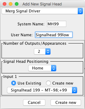
The MERG Signal driver in JMRI has been set up to control the SD2 Aspect output only.
It does not control the other features of the SD2 such as "Steam Rules" or "Feather",
however these can easily be configured using Logix or Routes.
Notes - The MERG SD2 driver does not support a Flashing yellow Aspect.
For Flashing yellow Aspects an additional circuit is required as documented in the MERG
Technical Bulletins.
As the MERG SD2 driver goes beyond the Green/Yellow/Red Aspects supported in JMRI with a
Double yellow (yellow over yellow) aspect, the Double yellow state is represented in the
status as a "Lunar".
Further information on the Merg Signal Driver can be found at MERG
Back to the Signal Head Table help page.